
Make your first shape
Open the Tools menu, go to Create Shapes, and pick Solid Shape. A flat, extruded shape appears in the 3D view. That single shape is the start of your part — everything else builds on top of it.
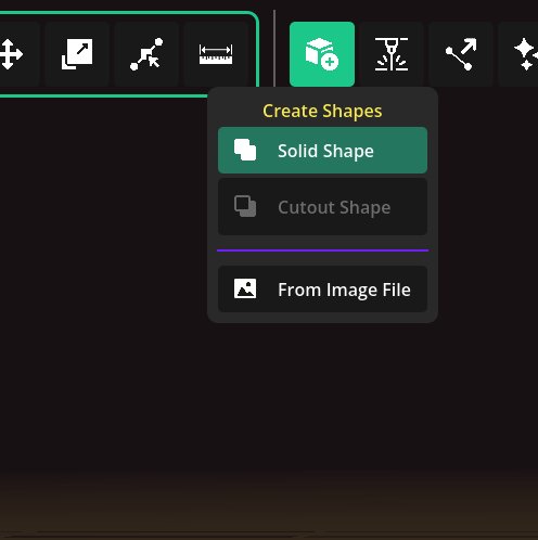
The Tools → Create Shapes menu.
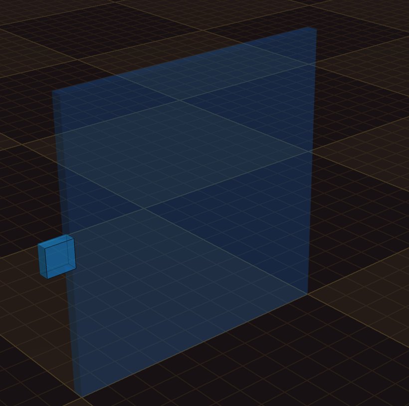
A brand-new solid shape in the 3D view.
Child shapes and the Outliner
With a shape selected, you can add child shapes to it. Children merge into the parent so the whole thing becomes one solid piece. This is how you grow a simple block into a detailed part.
The Outliner (the list panel) shows every shape and how they are nested. Click items here to select them and see the parent–child order.
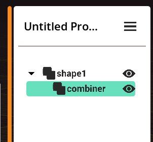
The Outliner shows the hierarchy — a shape with a child under it.
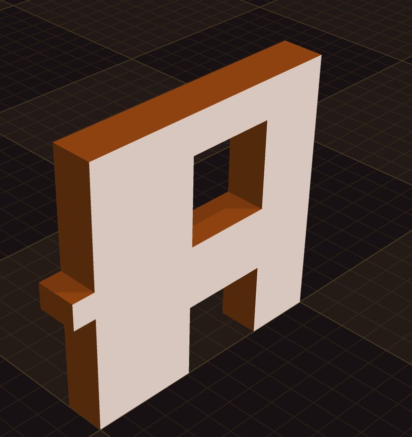
Children merge into the root shape as one solid piece.
The flat view (your SVG)
The side view shows the flat 2D layout of your part — exactly what gets cut. Child shapes always merge into the root as one outline. When you're ready, this view exports as an SVG you can send straight to a laser cutter.
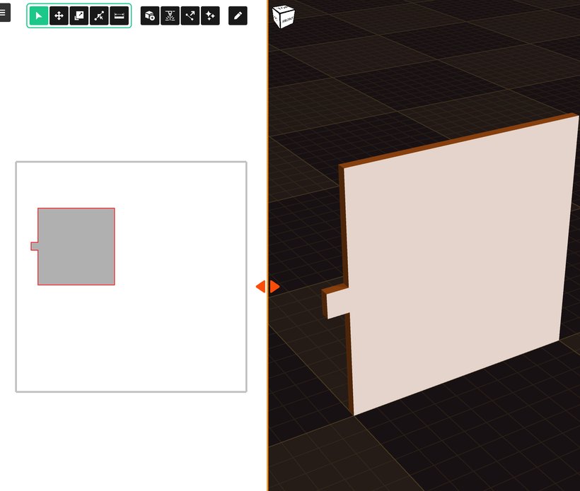
The flat side view — the 2D layout that becomes your SVG.
Cut holes with cutout shapes
Need a hole? Add a cutout shape instead of a solid one. Wherever it overlaps the part, it removes material, leaving a hole. Use cutouts for slots, windows, and openings.
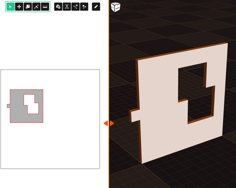
A cutout shape punches a hole through the panel.
Combine or cut
Any shape can either add to its parent or cut away from it. Select the shape and change its Type in the properties — Combine to merge, or Cut to subtract. You can switch this at any time, so you're never locked in.
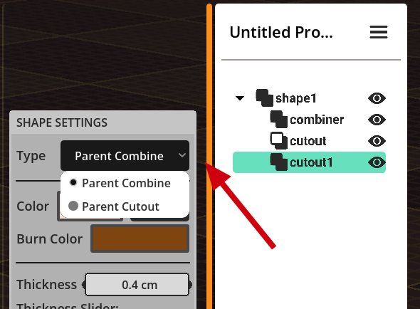
The Type dropdown — combine with, or cut out from, the parent shape.
Thickness and properties
Every shape has a Properties panel. The most important one is Thickness — set it to match your material (for example, 3 mm plywood). Change any property here to fine-tune your part.
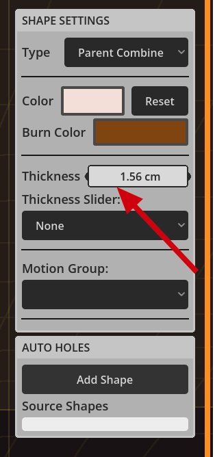
Shape Settings — set the Thickness to your material.
The Edit menu
Open the Edit menu button to Duplicate a shape, flip it, align its pivot, or mirror points. Not sure what a button does? Hover over it and a tooltip explains it. This works on almost every button in the app.
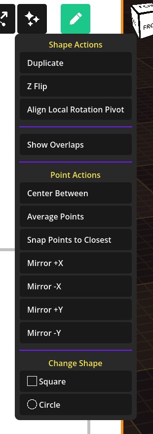
The Edit menu — duplicate, flip, mirror, and more.
Move and rotate
Turn on the Move tool, then click and drag the handles to move or rotate a shape. You can also type exact values into the Position and Rotation fields — these only show while the Move tool is on, and they read from the move gizmo in global space.
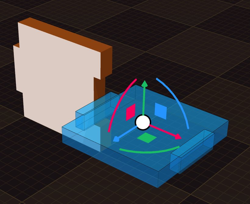
The Move tool gizmo — drag a handle to move or rotate.
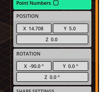
Position and Rotation fields for precise placement.
Edit points
Turn on the Points Editing tool to reshape a shape by its corners (vertices). You can add, move, and delete points — it works a lot like Illustrator. Click-drag to select several points at once, and use the properties to nudge or offset them. Points always move along the surface of the shape.
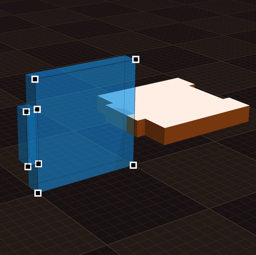
Editing the points of a shape.
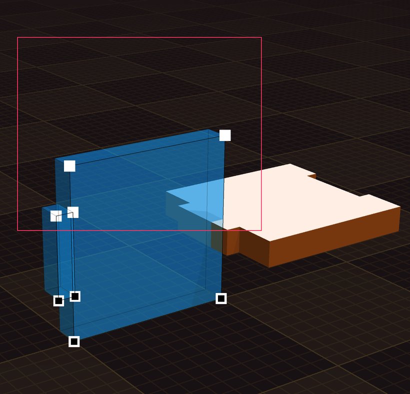
Click-drag to select multiple points.
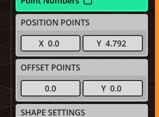
Type exact positions or offsets for the selected points.
Snapping
Turn on Enable Snap in Tool Settings. Now any point you move will snap-align to other points, so edges line up perfectly and parts fit together cleanly.
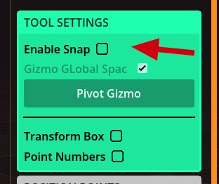
Enable Snap in Tool Settings.
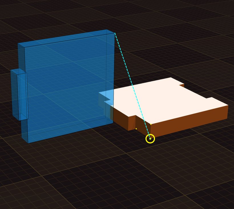
Parts line up exactly when snapping is on.
Place and snap the gizmo (V and S)
The Move tool has two power moves. Hold V and click to drop the gizmo pivot on any surface, point, or corner — handy for rotating around an exact spot. Hold S and drag from a point on your shape onto another point or surface, and the shape jumps there, rotated and positioned to match. It's a fast way to align pieces together.
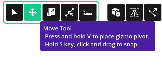
Hold V to place the pivot; hold S to snap onto a surface or point.
Tip: You can undo and redo anything with Ctrl + Z and Ctrl + Shift + Z.
Sliders: resize instantly
Sliders make your design parametric — drag one and the part resizes live. In the Controller menu, add a Slider. Click it to open its properties (min, max, and starting value).
To connect it: move the slider to a value, edit the shape to the form you want, then press Set State with the slider selected. The shape now takes that form at that value. Slide back and forth to watch it change — the real dimensions show in the 3D view as you drag. You choose what each value means; use a real measurement or any number you like.
You can hook up several sliders to one design — for example a box that adjusts in length, width, and height independently.
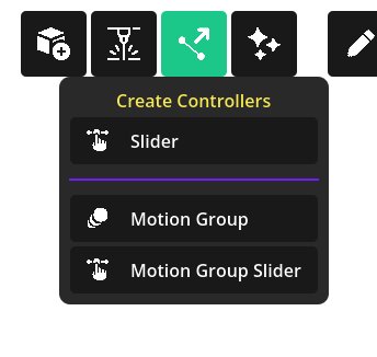
The Controller menu — add a Slider.
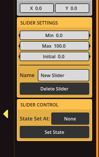
Slider settings, including the Set State button.
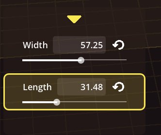
Separate Width and Length sliders resizing a part.
Moving parts (motion groups)
Some designs need to move — like a box with a hinged lid — so you can check the fit before cutting. Two tools handle this: a Motion Group and a Motion Group Slider.
First select the shapes that move together, then add a Motion Group (it appears in the Outliner). Each group has a pivot — the point it rotates around. Use Select Anchor Points to lock the pivot to one or more points; pick several and it sits at their center. The pivot stays glued to those points even when other sliders resize the object.
Now add a Motion Slider, select the group, and assign that slider to it. Set the slider's value, press Create New State, and move or rotate the group. Hit Done. The slider now drives that movement — as simple as that.
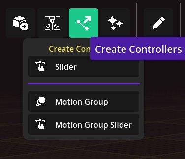
Add a Motion Group or Motion Group Slider from the Controllers menu.
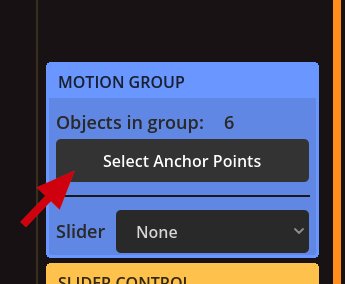
The Motion Group panel — Select Anchor Points and assign a slider.
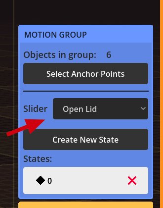
Assign the slider, then Create New State for the movement.
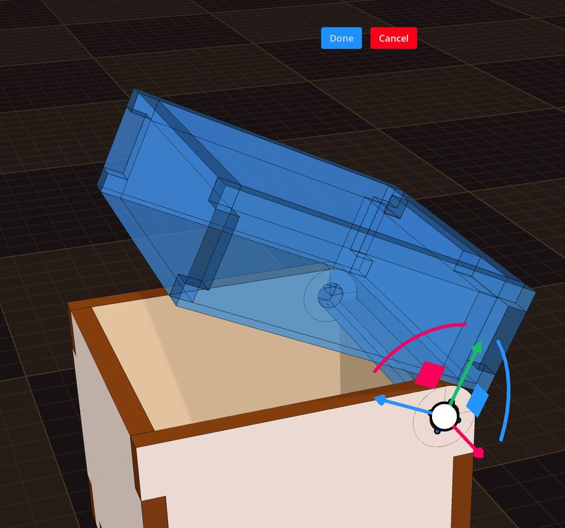
The slider drives the lid opening so you can test the design.
Arrange and export for cutting
In the 2D flat layout, drag your pieces around to pack them however you like on the sheet. When it looks right, press Export to save an SVG ready for your laser cutter. Any engraving you added is exported along with the cut lines.
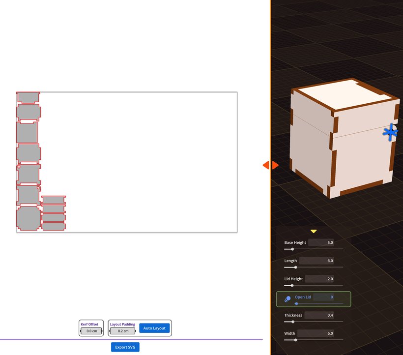
Arrange the pieces, then export a laser-ready SVG.
Text: letters you can cut
Open Create Shapes → Text and you get a word as a real shape — not a decal and not an engraving. The outline of every letter becomes geometry, so it extrudes to your material thickness, takes a color, and leaves the app as a cut line in your SVG.

Create Shapes → Text.

Two ways to use it: OPEN cut through the plate, MAKER standing on its own.
A new text shape arrives reading FlexCut3D in Roboto Bold. Select it and the purple Text panel appears where the Size panel normally sits — a text shape has no vertices to drag, because its outline comes from the font.

The Text panel. Spacing is greyed out while Auto-stick is on.
The text box takes anything you type, several lines included, and the shape follows as you type.
Font opens a drop-down that draws every entry in its own typeface, so you pick by looking instead of by name. Seven come with the app: Roboto Regular, Roboto Bold, Roboto Black, Coolvetica Hv Comp, DynaPuff, Pacifico and Sigmar.
Size is the line height in cm, not the height of the capitals. In Roboto Bold, Size 6.0 gives capitals 3.6 cm tall. Do not work that ratio out in your head — the real width and height in cm are printed next to the selection box and update as you type.
Line Spacing adds to the gap between lines, and it is allowed to go negative, so two stacked lines can overlap into one piece.
Spacing is manual letter spacing. It only does something with Auto-stick off.
Everything else works the way it does on any other shape: thickness, colors, the ruler, the gizmos, sliders, motion groups, Auto Holes and image engraving.
Auto-stick: one word, one piece
Cut a word with the letters sitting apart and the laser hands you loose letters — five of them for MAKER, face down and out of order. Auto-stick is the fix and it is on by default: each letter slides left until its outline really overlaps its neighbour by Overlap cm, so the word comes off the bed as one connected piece.

Same word, same size. Top: Auto-stick off, five separate pieces. Bottom: Auto-stick on, one.
The numbers behind that picture: MAKER at Size 6.0 in Roboto Bold measures 16.8 cm wide with Auto-stick off, and 14.8 cm with it on at Overlap 0.15. A space always resets the run, so separate words stay separate.
Turn Auto-stick off when the letters do not have to hold together — text sitting inside a panel that carries them, or text you are cutting as holes. Then set the gaps yourself with Spacing.
One thing to plan for either way: the middle of an O, an A or a P is its own piece of material. Cut a word as holes and those centres drop out. Pick a font with open counters, or keep the centres and glue them back.
Cut a word into a panel
Text always arrives as its own top-level shape. To punch it through a part instead of standing it up: drag the text onto that part in the Outliner so it becomes a child of it, then switch its Type to cut, exactly as in Combine or cut above. Position it with the gizmo.
Turn Auto-stick off first. Inside a panel the letters do not need to touch, and overlapping them only runs the holes together.
Engrave an image
You can add an image to any surface — even several. Open Effects → Image Engraving, upload a picture, and position it on the shape. It becomes a black-and-white engraving on that face, and it exports with the rest of your SVG.
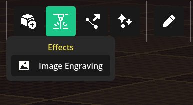
Effects → Image Engraving.
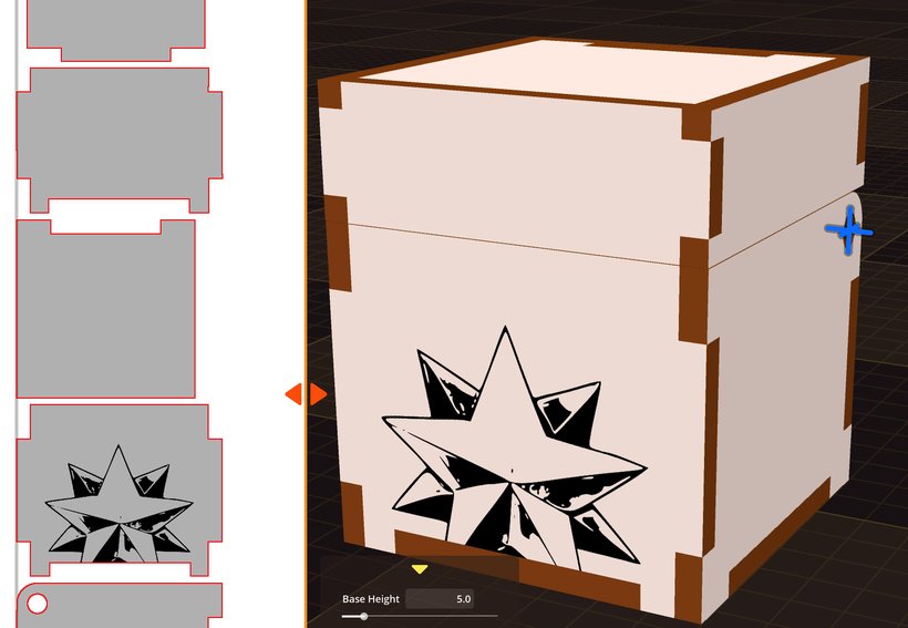
The engraving shown on the part's surface.
Auto holes
Every shape has an Auto Holes property that cuts fitting holes for you — no extra cutout shapes needed, which keeps your Outliner tidy. Select the shape that needs holes, then under Auto Holes choose the shape that should make them. Wherever the two overlap, a correctly-shaped hole is cut, at any angle, so everything slots together perfectly after cutting. Great for tab-and-slot joints and press-fits.
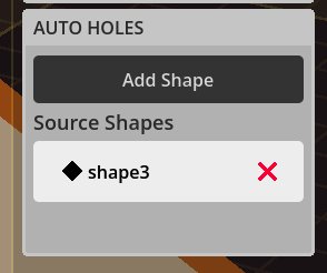
Pick the source shape that carves the holes.
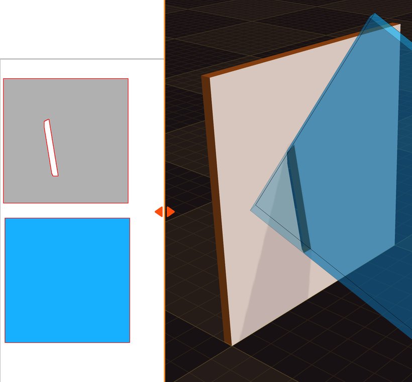
Parts fit together with holes cut automatically.
Control thickness with a slider
Thickness is just a property, so you can hook it up to a slider too. That lets you switch between materials of different thicknesses in one click — handy when the same design might be cut from 3 mm or 6 mm stock.
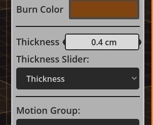
Drive Thickness from a slider to support multiple materials.
Drive an effect with a slider
Sliders already move points and swap thickness. They can drive the numbers on an Image Cutout or an Image Engraving too — Position, Size, Rotation, Edge Margin and Gap. That is how you make a pattern grow with the panel it sits on, from a single handle.
Add the effect and set it the way it should look at rest. Do this while every slider sits at its default — that resting look is what the slider drives away from.
Move the slider to one end of its range.
Change the effect. Drag the purple handles in the 3D view, or type into the fields.
Press Set State. The confirmation tells you how many effect parameters it captured. If it only says State Set, nothing differed from the resting values and nothing was stored.
Drag the slider back and forth.

One slider driving the cutout's size. Nothing else about the panel changed.
A small icon appears on every field a slider is driving. Click it and you get every slider in the project listed; the ones actually driving that field are the ones you can pick. Choose one to disconnect it, or Disconnect from all sliders to drop them in one go. Either way the number goes back to its resting value.

Size X and Y are driven here, so both carry the icon. Position and Rotation are not.
While you drag an effect's centre or a corner handle, the host shape's corner points appear as white dots and its centre as a blue ring. Bring the handle close and it snaps exactly onto one — the quick way to centre a pattern or line it up with an edge. Hold Ctrl while dragging to ignore them.
Two things worth knowing. Only one slider may be away from its default when you press Set State — reset the others first. And a driven value keeps going past what you captured: if a cutout is 5 cm at the middle of the range and 10 cm at the top, pushing the slider further keeps it growing.